Workshop Manual Specifications (13B-MSP)
Technical specifications extracted from the official Mazda RENESIS Rotary Engine Workshop Manual (Part No. 9999-95-E13B-MSP09, Ref. 1773-1U-03C, revised October 2008). These values apply to the 13B-MSP (Multi Side Port) engine as used in the RX-8.
Sources:
- RENESIS Rotary Engine Workshop Manual (complete PDF)
- Disassembly section | Inspection section | Rotor Assembly section
:::info Type A vs Type B The manual distinguishes two engine types based on VIN:
- Type A: All VINs except those listed below
- Type B: VINs starting with JM1FE172/174/17M/17P *9# 400001+ Type B corresponds to Series 2 (2009-2012) engines with revised oil system (6 oil injectors, higher pressure oil pump, OCV system). :::
Exploded Views Index
| Diagram | Source Page | Description |
|---|---|---|
| Housing Disassembly I | 01-10 p.4 | Oil pan, baffle plate, water pump, thermostat |
| Housing Disassembly II | 01-10 p.6 | Front cover, oil pump, pulley, chain |
| Housing Disassembly III | 01-10 p.8 | Main engine exploded view — flywheel, rotors, housings, e-shaft |
| Rotor Disassembly | 01-10 p.12 | Rotor seals — apex, side, corner, oil seals, springs |
| Rotor Assembly | 01-10 p.30 | Rotor reassembly — seal and spring installation order |
| Housing Assembly I | 01-10 p.34 | Main engine reassembly — housings, rotors, e-shaft, tension bolts |
| Housing Assembly II | 01-10 p.42 | Oil pump, front cover, pulley reassembly |
| SST Tools Overview | 01-60 p.1 | All Special Service Tools with photos |
1. Engine Identification
| Characteristic | Standard Power (4-port) | High Power (6-port) |
|---|---|---|
| Engine type | 13B-MSP | 13B-MSP |
| Compression ratio | 10.0:1 | 10.0:1 |
| Spark plugs (leading) | NGK RE7C-L | NGK RE7C-L |
| Spark plugs (trailing) | NGK RE9B-T | NGK RE9B-T |
(Workshop Manual)
2. Side Housing Inspection (Front, Intermediate, Rear)
Side Housing Inspection Diagram
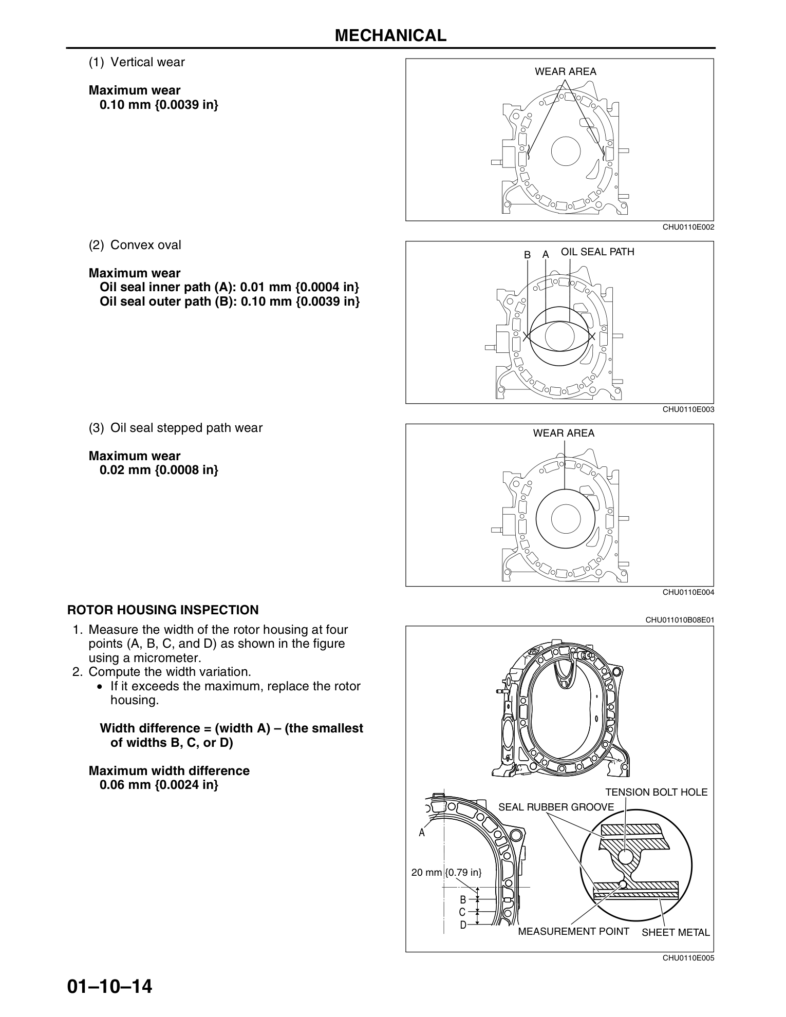
2.1 Distortion
| Parameter | Specification |
|---|---|
| Maximum distortion | 0.04 mm (0.0016 in) |
Measured at four positions using a straight edge and feeler gauge. Replace the housing if distortion exceeds 0.04 mm.
2.2 Wear (Rotor Contact Area)
| Wear Type | Maximum |
|---|---|
| Vertical wear | 0.10 mm (0.0039 in) |
| Convex oval - oil seal inner path (A) | 0.01 mm (0.0004 in) |
| Convex oval - oil seal outer path (B) | 0.10 mm (0.0039 in) |
| Oil seal stepped path wear | 0.02 mm (0.0008 in) |
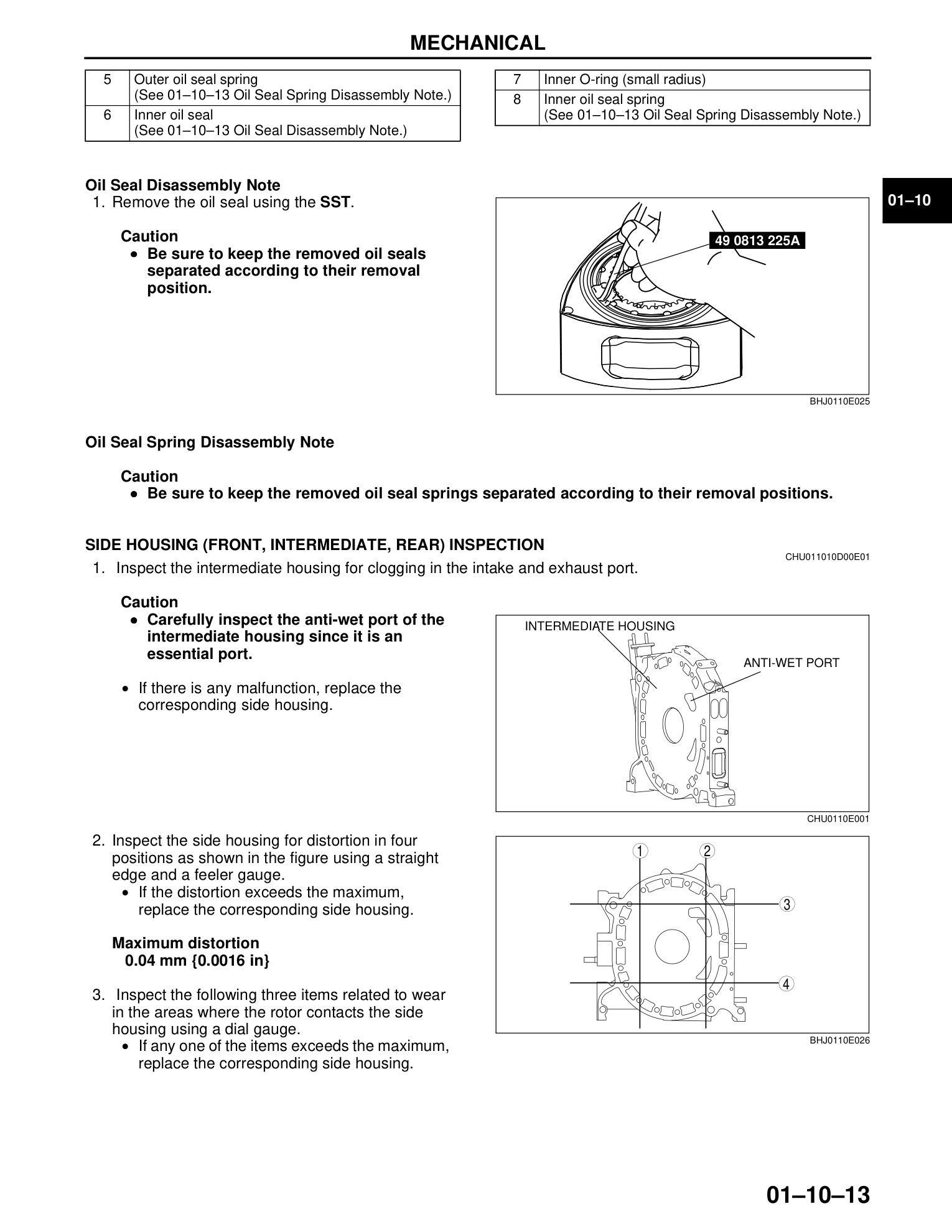
:::caution Anti-Wet Port Carefully inspect the anti-wet port on the intermediate housing — it is essential for proper engine operation. If clogged, replace the housing. :::
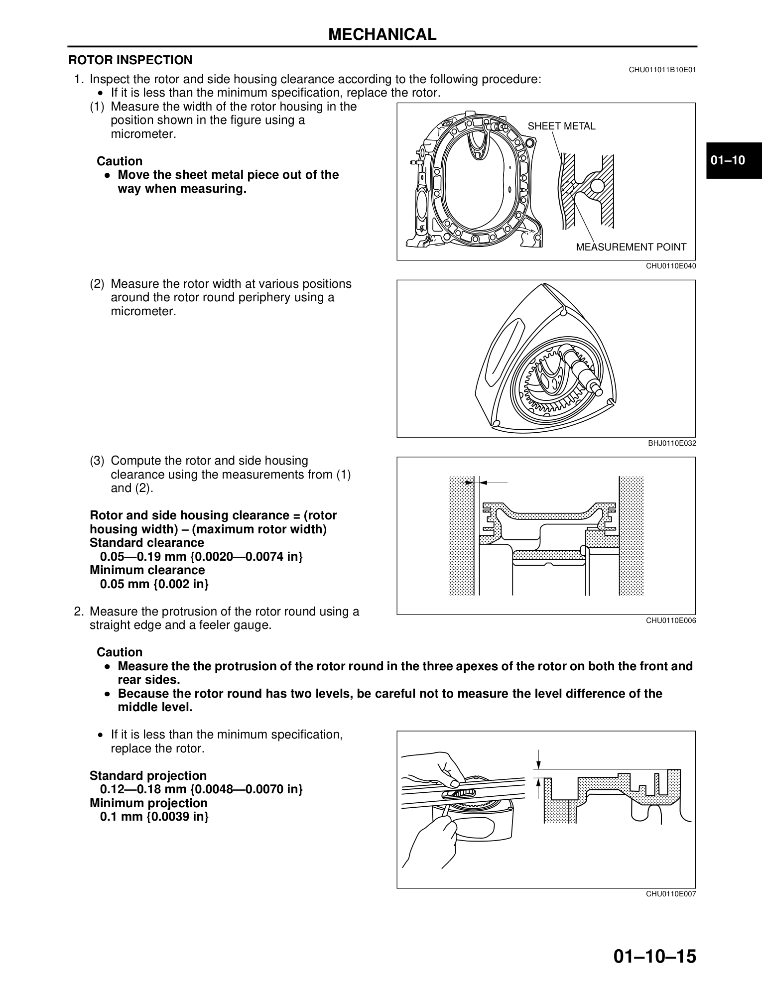
3. Rotor Housing Inspection
Rotor Housing Inspection Diagram
| Parameter | Specification |
|---|---|
| Maximum width difference (A vs smallest of B/C/D) | 0.06 mm (0.0024 in) |
Width is measured at four points (A, B, C, D) using a micrometer. Point A is 20 mm from the tension bolt hole.
4. Rotor Inspection
Rotor Inspection Diagram
4.1 Rotor and Side Housing Clearance
| Specification | |
|---|---|
| Standard clearance | 0.05–0.19 mm (0.0020–0.0074 in) |
| Minimum clearance | 0.05 mm (0.002 in) |
Calculation: clearance = rotor housing width − maximum rotor width
Move the sheet metal piece out of the way when measuring rotor housing width.
4.2 Rotor Round Protrusion
| Specification | |
|---|---|
| Standard projection | 0.12–0.18 mm (0.0048–0.0070 in) |
| Minimum projection | 0.10 mm (0.0039 in) |
Measure on both front and rear sides, at all three apexes of the rotor. Be careful not to confuse the two levels of the rotor round.
4.3 Apex Seal Groove Clearance
| Specification | |
|---|---|
| Standard clearance | 0.042–0.101 mm (0.0017–0.0039 in) |
| Maximum clearance | 0.15 mm (0.0059 in) |
Measure with a feeler gauge. If clearance exceeds 0.15 mm, replace the apex seal. If still out of spec after replacement, replace the rotor.
4.4 Corner Seal Groove Inspection
Use SST 49 0839 165 (corner seal gauge):
- If 1/2 or more of either end can be inserted into the groove → replace the corner seal
- If 1/2 or more of both ends can be inserted → replace the rotor
When replacing corner seals, match the S or L inscription on the rotor.
5. Seal Specifications
5.1 Apex Seal
Apex Seal Inspection Diagram
| Parameter | Standard | Minimum |
|---|---|---|
| Apex seal height | 5.3 mm (0.20 in) | 4.3 mm (0.17 in) |
| Apex seal spring height | 5.4 mm (0.213 in) | 3.5 mm (0.148 in) |
Always replace the apex seal spring when replacing the apex seal.
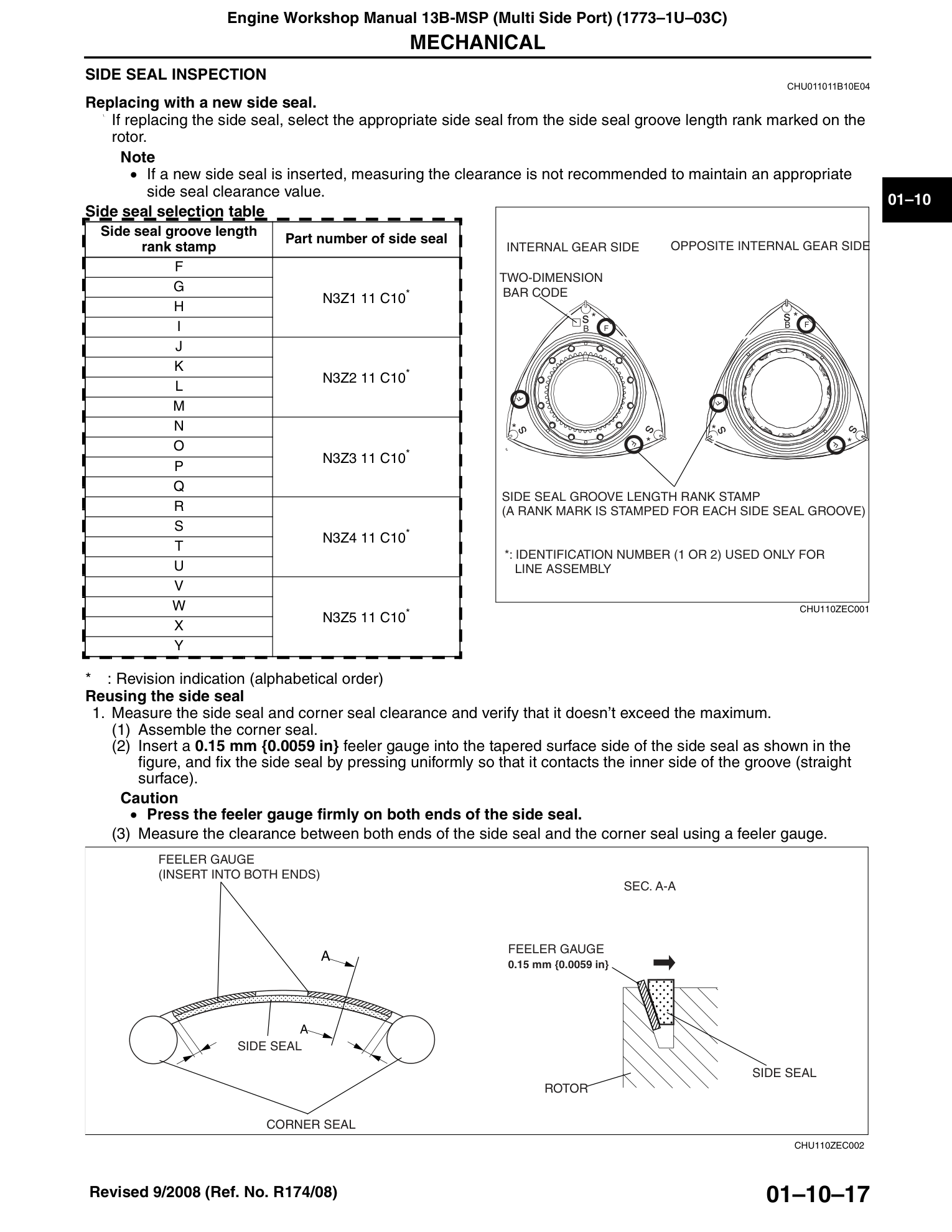
5.2 Side Seal
When replacing with a new side seal, select from the side seal groove length rank stamped on the rotor:
| Rank Stamp | Part Number |
|---|---|
| F, G, H, I | N3Z1 11 C10* |
| J, K, L, M | N3Z2 11 C10* |
| N, O, P, Q | N3Z3 11 C10* |
| R, S, T, U | N3Z4 11 C10* |
| V, W, X, Y | N3Z5 11 C10* |
* = Revision indication (alphabetical order)
If a new side seal is installed, measuring the clearance is NOT recommended (to maintain appropriate clearance value).
When reusing a side seal:
- Maximum side seal-to-corner seal clearance (sum of both ends): 0.4 mm (0.016 in)
5.3 Cut-Off Seal
| Parameter | Standard | Minimum |
|---|---|---|
| Height | 3.95 mm (0.1555 in) | 3.8 mm (0.15 in) |
| Spring projection | — | 0.5 mm (0.02 in) |
5.4 Side Seal Spring
| Parameter | Minimum |
|---|---|
| Projection (installed) | 0.5 mm (0.02 in) |
5.5 Corner Seal Spring
| Parameter | Minimum |
|---|---|
| Projection (installed) | 0.5 mm (0.02 in) |
5.6 Oil Seal
| Parameter | Maximum |
|---|---|
| Contact width (lip) | 0.5 mm (0.02 in) |
| Circumferential lip damage width | 2.5 mm (0.098 in) or 10+ nicks |
5.7 Oil Seal Projection (Rotor Assembly)
| Parameter | Specification |
|---|---|
| Oil seal projection (installed in rotor) | 0.5–0.6 mm (0.020–0.023 in) |
6. Eccentric Shaft (E-Shaft) Specifications
6.1 Runout
| Specification | |
|---|---|
| Standard runout | 0.02 mm (0.0008 in) |
| Maximum runout | 0.06 mm (0.0024 in) |
Set the main journals on V-blocks and a surface plate. Measure runout at the end of the shaft using a dial gauge.
6.2 End Play
| Specification | |
|---|---|
| Standard end play | 0.04–0.09 mm (0.0016–0.0035 in) |
Adjust using spacers of varying thickness:
| Marking | Dimension (mm) |
|---|---|
| A | 7.985 |
| B | 8.005 |
| C | 8.025 |
| D | 8.045 |
| E | 8.065 |
If end play is not within specification even after installing an A-marked spacer, grind it and reuse.
6.3 Pulley Lockbolt Torque
| Parameter | Torque |
|---|---|
| Pulley lockbolt | 300–340 N·m (30.6–34.6 kgf·m, 222–250 ft·lbf) |
| Pulley boss bolt | 14.2–17.2 N·m (1.45–1.75 kgf·m, 10.5–12.6 ft·lbf) |
6.4 Eccentric Shaft Bypass Valve
| Parameter | Specification |
|---|---|
| Minimum projection at 60°C (140°F) oil temp | 6 mm (0.24 in) |
7. Bearing Clearances
7.1 Rotor Bearing Oil Clearance
| Specification | |
|---|---|
| Standard clearance | 0.06–0.08 mm (0.0024–0.0030 in) |
| Maximum clearance | 0.10 mm (0.0039 in) |
Rotor bearing oil clearance = rotor bearing inner diameter − rotor journal outer diameter.
Measure the rotor journal slightly off-center, as the center section is raised and does not contact the bearing.
If clearance exceeds 0.10 mm, replace the rotor bearing. If still out of spec after replacement, replace the eccentric shaft.
7.2 Main Bearing Oil Clearance
| Configuration | Standard | Maximum |
|---|---|---|
| Without stopper screw | 0.045–0.085 mm (0.0018–0.0033 in) | 0.10 mm (0.0039 in) |
| With stopper screw | 0.055–0.075 mm (0.0022–0.0029 in) | 0.10 mm (0.0039 in) |
If clearance exceeds the maximum, replace the main bearing. If still out of spec after replacement, replace the eccentric shaft.
7.3 Pilot Bearing (MT only)
| Parameter | Specification |
|---|---|
| Installation depth (bearing) | 11.5–12.25 mm (0.4528–0.4822 in) |
| Installation depth (oil seal) | 5.5–6.3 mm (0.217–0.248 in) |
8. Oil Pump Specifications
Type A (Series 1)
| Parameter | Standard | Maximum |
|---|---|---|
| Body clearance (outer rotor to body) | 0.20–0.25 mm (0.0079–0.0098 in) | 0.30 mm (0.0118 in) |
| Tip clearance (inner to outer rotor) | 0.03–0.12 mm (0.0012–0.0047 in) | 0.15 mm (0.0059 in) |
| Side clearance (rotor to housing) | 0.03–0.125 mm (0.0012–0.0049 in) | 0.15 mm (0.0059 in) |
Type B (Series 2)
The Type B oil pump is a non-serviceable precision unit. If any malfunction occurs, replace the entire oil pump assembly.
9. Critical Torque Specifications
9.1 Housing Assembly
| Fastener | Torque |
|---|---|
| Tension bolts | 31.4–39.2 N·m (3.21–3.99 kgf·m, 23.2–28.9 ft·lbf) |
| Flywheel locknut (MT) | 392–490 N·m (40.0–49.9 kgf·m, 290–361 ft·lbf) |
| Counterweight locknut (AT) | 392–490 N·m (40.0–49.9 kgf·m, 290–361 ft·lbf) |
| Oil pan drain plug (Type A) | 29.4–39.2 N·m (3.00–3.99 kgf·m, 21.7–28.9 ft·lbf) |
| Oil pan drain plug (Type B) | 29.4–41.2 N·m (3.00–4.20 kgf·m, 21.7–30.3 ft·lbf) |
| Pulley lockbolt | 300–340 N·m (30.6–34.6 kgf·m, 222–250 ft·lbf) |
9.2 Front Cover and Oil Pump
| Fastener | Torque |
|---|---|
| Front cover bolts | 18.6–25.5 N·m (1.90–2.60 kgf·m, 13.8–18.8 ft·lbf) |
| Oil pump sprocket locknut | 31.4–46.1 N·m (3.21–4.70 kgf·m, 23.2–34.0 ft·lbf) |
| Oil pump drive gear nut | 254–294 N·m (25.9–29.9 kgf·m, 188–216 ft·lbf) |
| Main bearing stopper screw | 3.2–4.7 N·m (33–47 kgf·cm, 29–41 in·lbf) |
9.3 External Components
| Fastener | Torque |
|---|---|
| Oil pan bolts (Type A) | 7.8–10.8 N·m (80–110 kgf·cm, 69–95.5 in·lbf) |
| Oil pan upper block bolts (Type B) | 18.6–25.5 N·m (1.9–2.6 kgf·m, 13.8–18.8 ft·lbf) |
| Oil pan bolts (Type B) | 7.8–10.8 N·m (80–110 kgf·cm, 69–95.5 in·lbf) |
| Thermostat housing | 18.6–25.5 N·m (1.90–2.60 kgf·m, 13.8–18.8 ft·lbf) |
| Water pump bolts | 18.6–25.5 N·m (1.90–2.60 kgf·m, 13.8–18.8 ft·lbf) |
| Oil jet plug | 3.9–11.7 N·m (40–119 kgf·cm, 35–103 in·lbf) |
| Engine hanger bolts | 31.4–46.1 N·m (3.21–4.70 kgf·m, 23.2–34.0 ft·lbf) |
10. Oil Seal Spring Identification Colors
During rotor assembly, oil seal springs must be installed with the correct orientation. The identification colors indicate position:
| Position | Front Rotor | Rear Rotor | ||
|---|---|---|---|---|
| Engine Front Side | Engine Rear Side | Engine Front Side | Engine Rear Side | |
| Inner spring | White | Blue | White | Blue |
| Outer spring | White + Pink | Blue + Pink | White + Pink | Blue + Pink |
If the identification color is not visible on reused springs: assemble with the rounded end towards the rotor side and the squared end upward. Position the rounded end within 0–15 mm of the oil seal spring rotation lock.
11. Assembly Notes and Critical Procedures
11.1 Tension Bolt Tightening Order
Tension Bolt Tightening Order Diagram
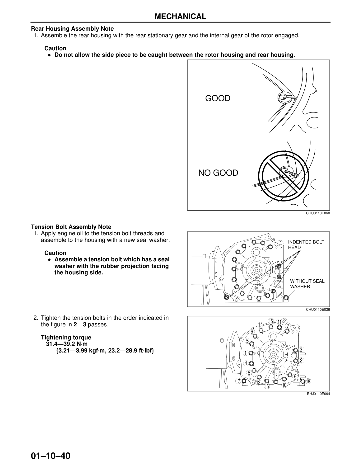
Tension bolts must be tightened in the numbered sequence shown in the workshop manual (2–3 passes):
 9  8  7
 5  4  3
10  1
18 17 15 16 14 13
11
 6  2
12
Always apply engine oil to tension bolt threads. Always use new seal washers (rubber projection facing the housing side).
11.2 Front Cover Bolt Tightening Order
Tighten in this sequence:
7  5  4  3
   1  2
6
11.3 Silicone Sealant Application
When applying silicone sealant (oil pan, oil pan upper block, rotor housing joints):
- Bead thickness: 2.5–6.5 mm (0.10–0.26 in)
- Apply in a single unbroken line around the entire perimeter
- Install parts within 5 minutes of applying sealant
- Clean old sealant from bolts before reuse — old sealant on bolts can cause housing cracks
11.4 Eccentric Shaft End Play Measurement
- Assemble spacer, needle bearing, thrust plate, balance weight, oil pump drive gear, and metering oil pump drive gear (Type A)
- Assemble pulley, position plate, and pulley boss
- Tighten pulley lockbolt to 300–340 N·m
- Measure end play with dial gauge: 0.04–0.09 mm
11.5 Rotor Housing Seal Rubber
Rotor Housing Assembly Diagram
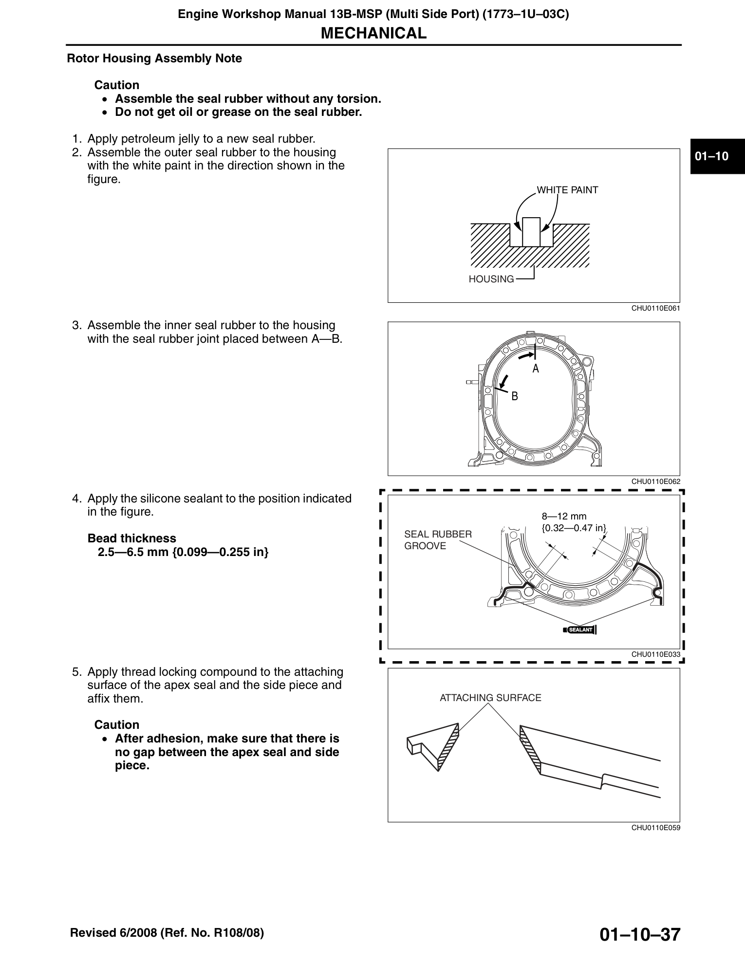
- Apply petroleum jelly to new seal rubber
- Outer seal rubber: white paint facing direction shown in manual
- Inner seal rubber: joint placed between points A–B
- Do not get oil or grease on the seal rubber
12. Special Service Tools (SST)
SST Tools Overview Diagram
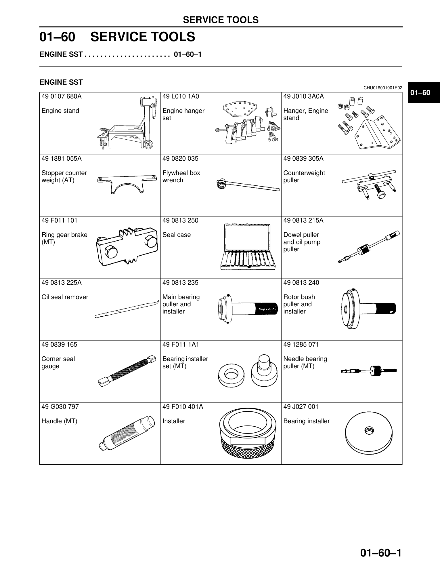
The following Mazda SSTs are required for proper engine service:
| SST Reference | Description | Purpose |
|---|---|---|
| 49 0107 680A | Engine stand | Engine support |
| 49 L010 1A0 | Engine hanger set | Lifting and mounting |
| 49 J010 3A0A | Engine stand hanger | Alternative lifting |
| 49 1881 055A | Counterweight stopper (AT) | Locking flywheel/counterweight |
| 49 F011 101 | Ring gear brake (MT) | Locking flywheel |
| 49 0820 035 | Flywheel box wrench | Flywheel locknut |
| 49 0839 305A | Counterweight puller | Counterweight removal |
| 49 0813 250 | Seal case | Organizing seals during disassembly |
| 49 0813 215A | Dowel puller / oil pump puller | Dowel and pump removal |
| 49 0813 225A | Oil seal remover | Oil seal extraction |
| 49 0813 235 | Main bearing puller and installer | Main bearing R&R |
| 49 0813 240 | Rotor bush puller and installer | Rotor bearing R&R |
| 49 0839 165 | Corner seal gauge | Corner seal groove inspection |
| 49 F011 1A1 | Bearing installer set (MT) | Pilot bearing installation |
| 49 1285 071 | Needle bearing puller (MT) | Pilot bearing removal |
| 49 G030 797 | Handle (MT) | Bearing installer handle |
| 49 F010 401A | Installer | Front oil seal installation |
| 49 J027 001 | Bearing installer | Rear oil seal installation |
:::tip Aftermarket Alternatives Many SSTs can be substituted with generic tools. See the Rebuild Guide for recommended aftermarket equivalents. :::
13. General Workshop Practices (from Section 00)
Parts That Must Always Be Replaced
The workshop manual mandates replacement of the following parts upon removal:
- Oil seals
- Gaskets
- O-rings
- Lock washers
- Cotter pins
- Nylon nuts
Torque Formula (SST + Torque Wrench)
When using a torque wrench with an SST, recalculate:
Torque = Specified Torque × [L / (L + A)]
Where:
- L = Length of the torque wrench
- A = Length of the SST past the torque wrench drive
14. Fluid Capacities and Vehicle Specifications
Specifications from the 2011 Mazda RX-8 Owner's Manual and 2010 Mazda Specification Deck (MNAO).
Fluid Capacities
| Fluid | Capacity |
|---|---|
| Engine oil (with filter) | 4.4 L (4.6 US qt, 3.9 Imp qt) |
| Engine oil (without filter) | 4.2 L (4.4 US qt, 3.7 Imp qt) |
| Engine coolant (MT) | 10.0 L (10.6 US qt, 8.8 Imp qt) |
| Engine coolant (AT) | 9.8 L (10.4 US qt, 8.6 Imp qt) |
| Manual transmission oil | 1.95 L (2.1 US qt, 1.7 Imp qt) — API GL-4, 75W-90 |
| Automatic transmission fluid | 8.0 L (8.5 US qt, 7.1 Imp qt) — JWS3309 / ATF M-V |
| Rear differential oil | 1.3 L (1.4 US qt, 1.1 Imp qt) — API GL-5 |
| Fuel tank | 64.0 L (16.9 US gal) |
| Brake fluid | DOT 3 |
| A/C refrigerant | HFC-134a (R-134a) |
(2011 Owner's Manual)
Spark Plugs
| Position | Part Number (Mazda) | NGK Equivalent | Gap |
|---|---|---|---|
| Leading (lower) | N3Y1 / N3H1 | RE7C-L | 1.15–1.25 mm (0.045–0.049 in) |
| Trailing (upper) | N3Y8 / N3Y9 / N3H5 | RE9B-T | 1.15–1.25 mm (0.045–0.049 in) |
Replace all 4 spark plugs as a set. Do not mix leading and trailing plugs — they have different heat ranges (7 vs 9).
Vehicle Dimensions
| Dimension | Value |
|---|---|
| Length | 4,460 mm (175.6 in) |
| Width | 1,770 mm (69.7 in) |
| Height | 1,340 mm (52.8 in) |
| Wheelbase | 2,700 mm (106.3 in) |
| Track (front, 18" wheels) | 1,500 mm (59.1 in) |
| Track (rear, 18" wheels) | 1,505 mm (59.3 in) |
| Track (front, 19" wheels) | 1,505 mm (59.3 in) |
| Track (rear, 19" wheels) | 1,510 mm (59.4 in) |
| Curb weight (MT) | ~1,350 kg (2,976 lb) |
| Curb weight (AT) | ~1,375 kg (3,031 lb) |
| GVWR (MT) | 1,732 kg (3,818 lb) |
| GVWR (AT) | 1,752 kg (3,862 lb) |
| Payload | 308 kg (680 lb) |
| Trunk capacity | 290 L (7.6 cu ft) |
| Cd (Sport / GT) | 0.29 |
| Cd (R3) | 0.30 |
(2011 Owner's Manual, Car and Driver)
Chassis Specifications
| Component | Specification |
|---|---|
| Front suspension | Double wishbone (forged aluminum arms) |
| Rear suspension | Multi-link (tubular arms) |
| Stabilizer bar (front) | 26.5 mm |
| Stabilizer bar (rear) | 16.0 mm |
| Brakes (front) | 12.7" (322 mm) ventilated disc |
| Brakes (rear) | 11.9" (302 mm) ventilated disc |
| Steering | Rack and pinion, 2.9 turns lock-to-lock |
| Driveshaft (MT) | Carbon fiber |
| Final drive (MT, 2004-2008) | 4.444 (LSD) |
| Final drive (MT, 2009-2011) | 4.777 (LSD) |
| Final drive (AT) | 4.300 |
| Tire size (18") | 225/45R18 91W |
| Tire size (19") | 225/40R19 89W |
| Tire pressure | 220 kPa (32 psi) cold |
| Battery | 12V — 55 AH / 5 hr |
Engine Output by Year (US Market)
| Year | Transmission | Power | Torque | Redline |
|---|---|---|---|---|
| 2004–2005 | 6MT (6-port) | 238 hp @ 8,500 rpm | 159 lb-ft @ 5,500 rpm | 9,000 rpm |
| 2004–2005 | 4AT (4-port) | 197 hp @ 7,200 rpm | 164 lb-ft @ 5,000 rpm | 7,500 rpm |
| 2006–2008 | 6MT (6-port) | 232 hp @ 8,500 rpm | 159 lb-ft @ 5,500 rpm | 9,000 rpm |
| 2006–2008 | 6AT (6-port) | 212 hp @ 7,500 rpm | 159 lb-ft @ 5,500 rpm | 7,500 rpm |
| 2009–2011 | 6MT (6-port) | 232 hp @ 8,500 rpm | 159 lb-ft @ 5,500 rpm | 9,000 rpm |
| 2009–2011 | 6AT (6-port) | 212 hp @ 7,500 rpm | 159 lb-ft @ 5,500 rpm | 7,500 rpm |
:::info Power Rating Change US power ratings dropped from 238 hp to 232 hp between 2004 and 2006 due to the adoption of the SAE J1349 standard for engine power measurement, not an actual loss of power. The 4-speed automatic was replaced by a 6-speed Sport AT with paddle shifters starting in 2006. :::
Note: The 2004-2005 4AT was initially rated at 197 hp but was later revised to 189 hp under the SAE J1349 standard. The 6AT (introduced 2006) uses a 6-port engine.
Gear Ratios
| Gear | Manual (6MT) | Automatic (6AT) |
|---|---|---|
| 1st | 3.815 | 3.520 |
| 2nd | 2.260 | 2.045 |
| 3rd | 1.636 | 1.361 |
| 4th | 1.263 | 1.000 |
| 5th | 1.000 | 0.756 |
| 6th | 0.787 | 0.585 |
| Reverse | 3.714 | 3.714 |
| Final drive (2004-2008) | 4.444 | 4.300 |
| Final drive (2009-2011) | 4.777 | 4.300 |
(2010 Mazda Spec Deck)
15. Bearing and Front Cover Reference
From Bearing & Front Cover Reference Dimensions. Critical for engine rebuilds — bearings are selected by measuring and matching to the correct color-coded size.
Stationary Bearings (Main Bearings)
| Size (mm) | Part Number | Color Code |
|---|---|---|
| 1.980 | NF01-10-E04 | Yellow |
| 1.983 | NF01-10-E05 | Green |
| 1.986 | NF01-10-E06 | Brown |
| 1.988 | NF01-10-E22 | Yellow |
| 1.989 | NF01-10-E07 | Black |
| 1.991 | NF01-10-E23 | Green |
| 1.992 | NF01-10-E08 | Blue |
| 1.994 | NF01-10-E24 | Brown |
| 1.997 | NF01-10-E25 | Black |
| 2.000 | NF01-10-E26 | Blue |
Rotor Bearings
| Size (mm) | Part Number | Color Code |
|---|---|---|
| 3 mm (−0.005 to −0.010) | N3A1-11-B11 | Yellow |
| 3 mm (−0.000 to −0.005) | N3A2-11-B11 | Green |
| 3 mm (−0.000 to +0.005) | N3A1-11-B11 | Black |
Front Cover Spacers (E-Shaft End Play)
The spacer letter (A–E) determines e-shaft end play. Refer to Section 6.2 for the measurement procedure.
| Marking | Dimension (mm) |
|---|---|
| A | 7.985 |
| B | 8.005 |
| C | 8.025 |
| D | 8.045 |
| E | 8.065 |
All specifications sourced from the official Mazda RENESIS Rotary Engine Workshop Manual (1773-1U-03C, revised October 2008) and the 2011 RX-8 Owner's Manual. Always refer to the latest version of the workshop manual for your specific vehicle.